一、 软件安装
1. 首先,安装NIOS II 开发包。采用虚拟光驱软件,如DAEMON 等将NIOS II V1.0 BUILD316E.ISO 文件映射到虚拟光驱上;
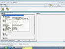
点击光驱图标,会自动运行安装程序

选择第一个选项,Install;
选择 Next 按钮;
询问是否接收协议的时候,选择 Yes,下一个也按Yes,继续;

如果是初学者,最后一个选项可以不选, Examples 可以选择自己熟悉的语言,其他选项建议都选上;
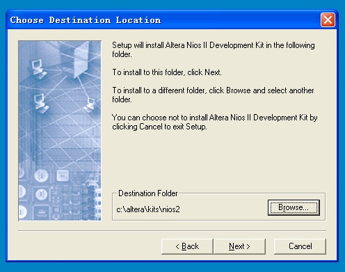
选择 QuartusII 的安装目录,如果不是C:盘,那么从Browse 选项中指定。如e:alterakits ios2;
接下来是选择一个程序组,一般情况按 Next 就可以了;
开始安装,大约需要几分钟时间拷贝文件;
点击 Finish,弹出一个IE 格式的说明文档,建议大家仔细看看Example Designs 选项,可以对NIOS II CPU 的配置和例程有更多的了解,对于以后的调试会很有帮助;
这样,开发软件就安装完毕了,赶快运行我们的第一个程序吧。
二、 Hello LED 程序调试
1. 首先,备份Example 目录。因为我们要对目录中的文件进行修改,所以还是保留一份更好一些,一旦改坏了,还可以回复。进入目录 E:alterakits ios2(我的QuartusII 安装在E:盘了),备份example 目录,命名为example_old。
2. 进入 E:alterakits ios2examplesverilog iosII_cyclone_1c20,删除low_cost 目录,同时将我们提供的low_cost.rar 文件拷贝过来,同时加压缩,解出来一个同名的low_cost 目录。
3. 启动 QuartusII 4.1;选择File-》Open Project,或者Cntl+J,打开low cost 项目。

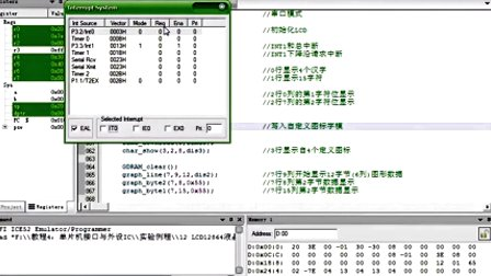
打开工程后,可以看到一个命名为 low_cost_1c20 的系统。通过View 菜单的最后一个选项可以选择是否显示管脚分配信息。
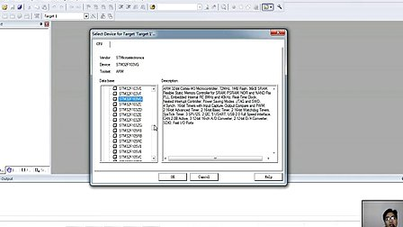
选择合适的芯片型号(EFA-CY1C6 为EP1C6Q240C8,EFA-CY1C6为EP1C12Q240C8):
A.选择菜单的 Assignments 菜单,然后选择第一项:Device。

B.

在Available device 中选择板上芯片的型号

出现以上对话框,一定要选择否,否则管脚分配就会丢失掉。
C.设置其他无用管脚。
首先选择Device & Pin Options,看到以下画面。

打开Unused Pins 标签,

选择第一项,所有无用的管脚置为输入状态,置为三态。
经过以上处理,就可以编译和下载程序了。
编译项目
从 Processing 菜单选Start compilation,或者Cntl+L,开始编译。出现警告信息可以不管,等待编译结束。
配置 FPGA
从Tools 菜单选择Programmer,选择JTAG 模式和对应的sof 文件,点击Start,
开始下载,如果成功,那么开始进入软件调试环境。
启动 NIOS II IDE 环境
关闭 Programmer,打开顶层文件。快捷方法就是点图标

双击 low_cost_1C20 系统模块,进入SOPC Builder。

选择 Run Nios II IDE,进入IDE 开发环境。
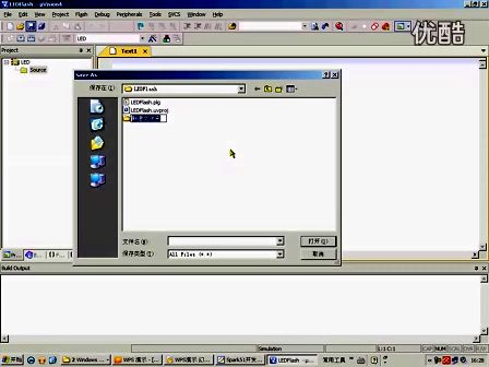
建立软件工程文件
选择 File-》New -》Project 选项。

选择 C/C++ Application, 点击Next。

从模板中选择 Hello LED,其他设置按默认设置,点击Finish。
编译工程文件
选中 hello_led_0,按右键,选择 Build Project
 ,
,
结束后,右下方的控制台会提示编译结束。

运行程序
从菜单中选择 Run-》Run…,弹出对话框

点击 New,会自动生成一个系统配置。

点击 Apply,然后点击Run。
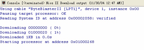
开始下载程序到 SDRAM,并运行起来。
观察板上的 4 个LED,大概没隔4 秒,LED 会轮流闪烁一次。
恭喜您,第一个 C 程序在NIOSII CPU 上已经运行起来了。
如果感兴趣,可以修改源文件,然后在编译,运行,看看 LED 有什么变化
以下是一个让 LED 闪烁更频繁的例子:
int main (void) __attribute__ ((weak, alias ("alt_main")));
/*
* Use alt_main as entry point for this free-standing application
*/
int alt_main (void)
{
alt_u8 led = 0x2;
alt_u8 dir = 0;
volatile int i;
/*
* Infinitly shift a variable with one bit set back and forth, and write
* it to the LED PIO. Software loop provides delay element.
*/
while (1)
{
if (led & 0x09) // 我们板上只有4个LED,所以当led的Bit3和Bit0有效的时候,
//就改变方向;
{
dir = (dir ^ 0x1);
}
if (dir)
{
led = led >> 1;
}
else
{
led = led << 1;
}
IOWR_ALTERA_AVALON_PIO_DATA(LED_PIO_BASE, led);
/*
* The delay element in this design has been written as a while loop
* to avoid confusing the software debugger. A tight, one line software
* delay loop such as:
* for(i=0; i<200000; i++);
* can cause problems when it is stepped through using a software
debugger.
* The while loop below produces the same behavior as the for loop shown
* above, but without causing potential debugger problems.
*/
i = 0;
while (i<100000) //加快闪烁间隔
i++;
}
return 0;
}